Figure L1: Aircraft in level flight. Lift from wings.
by Brooke P. Anderson (Brooke in Aces High), January 28, 2007
The purpose of this paper is to describe methods for calculating stall speed from data that you can obtain in a flight simulation program such as Aces High and methods for comparing that to stall-speed information from other sources (such as flight-test data or pilots' manuals).
If you spot errors in my analysis, I would welcome you to contact me at brooke@electraforge.com.
In the following, I will use text to write equations. I will use "*" to denote multiplication, "/" to denote division, and "^" to denote "to the power of", which is all generally familiar. I will use "_" to denote subscripts, as in "C_L_max", which is one variable or quantity, and where "C_L_max^2" would be the square of it.
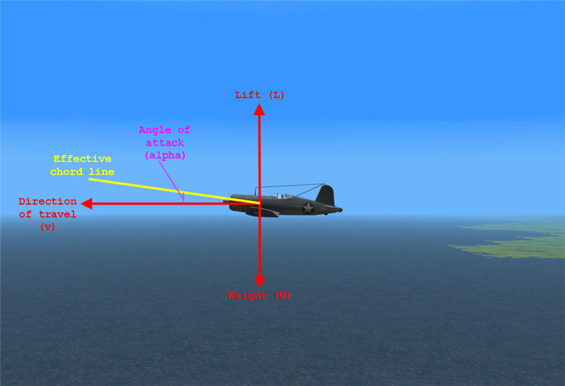
Figure L1: Aircraft in level flight. Lift from wings.
In level flight, the direction of travel of an aircraft (its velocity vector) is parallel to the surface of the earth. Define the direction of lift perpedicular to that. Wings generate increasing lift (up to stall) with increasing angles of attack. The angle of attack is the angle between the direction of travel and the chord line of the wings. A useful equation for lift from the wings is:
L = 0.5 * rho * v^2 * S * C_L,
where L is lift perpendicular to the direction of travel, rho is density of the air, v is the true airspeed of the aircraft along its direction of travel, S is the projected area of the wings (mean chord length times wingspan -- i.e., including area overlaid by nacelles and fuselage), and C_L is the coefficient of lift (which is approximately, although not altogether, independent of rho, v, and S). C_L increases with increasing angle of attack up to stall, and then it decreases. Thus, C_L_max happens at stall. Figure CL shows how C_L approximately behaves vs. alpha.

Figure CL: C_L vs. alpha (from http://www.grc.nasa.gov/WWW/K-12/airplane/incline.html).
If the airplane's engine is generating thrust, there can also be a contribution to total lift due from thrust. In Figure L2, the line of thrust is not parallel to the direction of travel. Thus, there is a component of thrust along the direction of lift: T * sin(phi), where phi is the angle between the line of thrust and the direction of travel. Thrust is typically along the centerline of the aircraft. Wings are mounted with some angle of incidence relative to the centerline -- typically 1-2 degrees for WWII fighters. Thus, phi is approximately angle of attack minus angle of incidence.
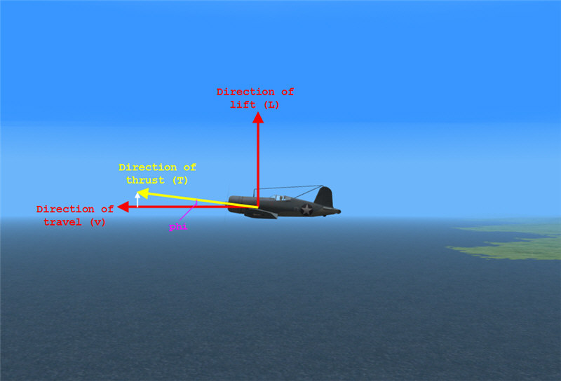
Figure L2: Aircraft in level flight. Contribution of thrust to total lift.
In level, steady flight, total lift equals weight of the aircraft. At stall, v is as low as it can be and still maintain level flight. Thus, in level flight at stall,
W = 0.5 * rho * v_stall^2 * S * C_L_max + T * sin(phi).
For power-off stalls, T can be approximated as zero:
W = 0.5 * rho * v_stall^2 * S * C_L_max.
This equation can be used to compute stall speed at a particular aircraft weight, when you know only stall speed at some other aircraft weight:
W_2 / W_1 = (v_stall_2 / v_stall_1)^2,
and thus we get (call it "Equation V1V2"):
v_stall_2 = sqrt(W_2 / W_1) * v_stall_1
For power-on stalls:
W = 0.5 * rho * v_stall^2 * S * C_L_max + T * sin(phi),
and we can estimate T * sin(phi).
At stall, alpha for most WWII wings is approximately 12-15 degrees with no flaps and 10-12 degrees with flaps (see [PH] p. 80, [BM] pp. 64-69, [RS] p. 229). Angle of incidence for WWII fighters is typically 1-2 degrees (see angle of incidence for various fighters in [FD]). Thus phi is approximately 14 degrees clean and 11 degrees with flaps down.
From propeller theory, and using 1 HP = 375 mi-lb/hr, we can get
T = eta * 375 * gamma * BHP / v,
where T is thrust in pounds, eta is propeller efficiency, gamma is a factor for how much of full power is being applied (1.0 for full power, 0.5 for half power, 0 for no power, etc.), BHP is the brake horsepower of the engine, and v is the aircraft velocity in miles/hour. eta depends on aircraft speed and properties of the particular propeller. It can be looked up for particular aircraft, or it can be estimated in a variety of ways (some better than others, of course).
However, for props with good ability to absorb the power of the engine, it can be approximated reasonably well by knowing the advance ratio (J) and the power coefficient (C_P):
J = 88.0 * v / (N * D),
where v is aircraft speed in mph, N is prop rotation in RPM, and D is prop diameter in feet; and
C_P = 52.5 * gamma* BHP / [(N / 1000)^3 * D^5 * rho / rho_0],
where gamma is fraction of full power being applied, BHP is engine brake horsepower, N is prop RPM, D is prop diameter in ft, rho is the air density, and rho_0 is the air density at standard sea level.
From propeller theory (see [PH] p. 139), eta_i / (1 - eta_i)^(1/3) = (pi / 2)^0.5 * J / C_P^(1/3), and eta is approx 0.85 to 0.87 eta_i. This gives the following chart (Figure 3-17 from [PH] p. 144), for eta vs. J/C_P^(1/3):
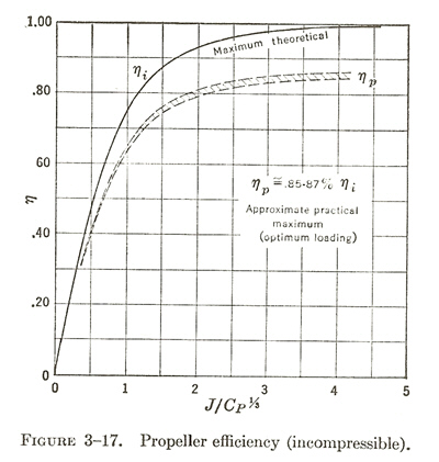
In most cases, near stall and at full power, eta is going to be about 0.6-0.65. As an example (similar to the F4U, F6F, and P-47), for an airplane with a 13 ft diameter prop, running at 2400 RPM at the engine, with a prop reduction gear of 2:1 (so prop at 1200 RPM), having its full 2000 HP (gamma = 1.0), and running at 100 mph (approximate stall speed of most WWII fighters), at sea level, we get J = 88 * 100 / (1200 * 13) = 0.56; C_P = 52.5 * 2000 / (1.2^3 * 13^5) = 0.16; and J/C_P^(1/3) = 1.03 from Figure 3-17. Under these conditions, eta is approx. 0.65. As another example (similar to the P-39, P-40, and P-51), for an airplane with a 11 ft diameter prop, running at 2400 RPM at the engine, with a reduction gear of 2:1 (so prop at 1200 RPM), having a full 1200 HP (gamma = 1.0), and running at 100 mph at sea level, we get J = 0.67; C_P = 0.23; J/C_P^(1/3) = 1.09; and eta is approx. 0.65 from Figure 3-17.
Altogether, a 2000 HP aircraft weighing 12,000 lbs (similar to an F4U), we'd get T * sin(phi) = 0.65 * 375 * 2000 / 100 * sin(14 deg) = 1180 lbs. This is for a stall with full power on -- it's as if the airplane is 1180 lbs lighter. From Equation V1V2, the effect on stall speed would be equivalent to v_stall_2 / v_stall_1 = sqrt(10820/12000) = 0.95 -- i.e., the approximate effect of full power is to reduce the stall speed by about 5%.
Near stall and at half power, eta is going to be about 0.7-0.75. Take the previous examples with gamma = 0.5. C_P is now 0.5 * 0.16 = 0.08 in example 1 and 0.5 * 0.23 = 0.12 in example 2. Then J/C_P^(1/3) is 1.30 in the first example and 1.36 in the second example, and eta is about 0.73 for both.
The usual method of determining stall speed experimentally with power off is to fly the aircraft level and to let it slow down progressively (while you maintain level flight) until the stall happens and to note the speed at which it happens. Stall here is judged typically by the nose rapidly dropping or, for aircraft where one wing stalls before the other, a wing rapidly dropping.
This is a reasonably good method, but there are some things that can throw off the results. If the plane is accelerating or decelerating along its direction of travel (as long as flight is still level and not accelerating up or down), it can cause problems in reading airspeed correctly at the moment of stall. If you are pulling (or pushing) g's, that can affect the point at which the stall happens. If the aircraft is at something other than g = 1 when the stall happens, the effective weight of the aircraft is no longer W, it is W * g. v_stall happens at 1 g. If you are at 1.2 g's (because you are trying to keep the plane level and so pulling and pushing slightly on the stick in an effort to keep it from gaining or losing altitude), v_stall_g = sqrt(1.2 * W / W) * v_stall = 1.095 * v_stall, or about 10% different from v_stall in level, 1 g flight.
The usual method of determining stall speed experimentally with power on is to fly the aircraft level, reduce power, let the aircraft slow down and approach power-off stall, then to add power little by little while continuing to fly level and continuing to slow down, getting on the "back side of the power curve" until you are at full throttle and near stall and to note the airspeed. This is sometimes hard to do in flight simulation of WWII fighters, which have powerful engines -- it is sometimes very hard to add power and not get into the situation where the aircraft is starting to accelerate and climb. Thus, with power on, there are the difficulties described above for power-off stall and these new difficulties.
It is often easier to maintain steady state near stall if allowing the aircraft to climb or descend. For power-on stalls, you don't have to be on the back side of the power curve -- you can be flying right near the stall with full power and in a climb. Likewise, for power-off stalls, you can be flying near the stall in a descent. In this way, you don't have to be continuously pulling more and more back pressure on the stick, and you can concentrate instead on just flying the edge of the stall, which makes it much easier to maintain close to 1 g.
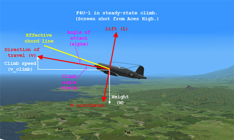
Figure L3: Aircraft in a steady-state climb.
The lift equation still applies in the coordinate system of the airplane (where v is along the direction of travel and L is the magnitude of the lift vector perpendicular to direction of travel).
L = 0.5 * rho * v^2 * S * C_L + T * sin(phi).
In this coordinate system, the magnitude of the weight vector opposite the lift vector (its projection onto the aircraft's coordinate system) is W * cos(theta). So, at stall speed (call it v_sc, for "v stall climb") in a steady-state climb we have:
W * cos(theta) = 0.5 * rho * v_sc^2 * S * C_L_max + T * sin(phi).
In a steady-state climb, the angle of climb (theta, the angle between the horizontal and the direction of travel), is calculated from the rate of climb (climb speed):
v_climb / v = sin(theta).
Usually, we will be more interested in cos(theta). At v_sc, this is (call it "Equation cos(theta)"):
cos(theta) = sqrt(1 - v_climb^2 / v_sc^2).
The formulas come out the same for descents as for climbs, except with v_climb replaced by v_descent.
Using the above, if we find that during a steady-state climb or descent, the plane stalls at a particular speed (v_sc), we can find the speed at which it would stall in level flight (call that v_stall) by:
W * cos(theta) = 0.5 * rho * v_sc^2 * S * C_L_max + T * sin(phi)
and
W = 0.5 * rho * v_stall^2 * S * C_L_max + T * sin(phi).
For T = 0 (power off), we get
cos(theta) = v_sc^2 / v_stall^2,
and we get (call it "Equation Vstall"):
v_stall = sqrt(1 / cos(theta)) * v_sc,
where cos(theta) is plugged in from Equation cos(theta).
Let L_T be defined as T * sin(phi). For T significantly not zero, we get
(W * cos(theta) - L_T) / (W - L_T) = v_sc^2 / v_stall^2,
and we get (call it "Equation Vstall2"):
v_stall = sqrt[(1 - L_T / W) / (cos(theta) - L_T / W)] * v_sc.
In conclusion, to find the stall speed in level flight based on the stall speed we are riding in a steady-state climb or descent, the key equations are:
1. L_T = T * sin(phi) = eta * 375 * gamma * BHP / v_sc * sin(phi),
where L_T is taken to be zero for power-off stalls and where eta is propeller efficiency, typically about 0.65 at stall speeds (but if you want to look it up or estimate it more precisely, see above), gamma is the fraction of full engine power that is being applied (zero for power-off stalls), BHP is the engine horsepower, v_sc is stall speed you are riding in mph, and phi is 14 degrees for clean and 11 degrees for full flaps;
2. cos(theta) = sqrt(1 - v_climb^2 / v_sc^2),
where v_climb is the velocity of climb or descent (in mph), and again v_sc is the stall speed we are maintining during the climb or descent;
and
3. v_stall = sqrt[(1 - L_T / W) / (cos(theta) - L_T / W)] * v_sc.
where v_stall is the equivalent stall speed we'd get in level flight, W is the gross weight of the aircraft, cos(theta) is from #2 above, and L_T is from #1 above.
Also, we can convert v_stall happening at one aircraft weight to v_stall that would happen at another aircraft weight by:
4. v_stall_2 = sqrt[(W_2 - L_T) / (W_1 - L_T)] * v_stall_1.
In Equations 1 and 2 above, v_sc and v_climb are true airspeeds. In Equations 3 and 4, airspeeds can either all be calibrated airspeeds or all be true airspeeds. (This is because v_true = f(air density) * v_calibrated, and so f() cancels out on either side of Equations 3 and 4 if you are using calibrated airspeeds on each side instead of true airspeeds on each side.)
To compare to stall-speed data in literature, you need the literature also to list some particulars. When literature lists a stall speed, you also need to know the aircraft weight (depends on fuel and ammo load) and the aircraft configuration (flap settings, gear up or down, power setting) at which the stall speed was obtained. You also need to know what sort of stall speed the literature is giving (true airspeed, indicated airspeed, or calibrated airspeed, for example), and if it the data is not for standard sea level conditions, what the conditions are (such as altitude).
It is important to note the difference between true airspeed, calibrated airspeed, and indicated airspeed. True airspeed is the true speed of the aircraft through the air. Indicated airspeed is what the aircraft's airspeed instrument shows. Calibrated airspeed is what the aircraft's airspeed instrument would show if it didn't have various forms of readout, positioning, or calibration error. In flight stimulators, calibrated airspeed and indicated airspeed are usually the same.
Some literature leaves out the aircraft weight. If you can't figure out what standard weight they are then using, that's a problem for comparing stall speeds. Most literature assumes the stall speed is at standard sea level conditions. Most will give aircraft configuration (although if it just lists "landing configuration", one is left to assume full flaps and landing gear as opposed to partial flaps and landing gear). Lots of literature, if it gives power-on stall data, does not say what the power settings are, again making the data not as useful as it could be. Lots of literature is not entirely clear on whether or not the "indicated airspeed" they give is actually indicated airspeed or calibrated airspeed. If it's indicated airspeed, ideally, you should compute the corresponding calibrated airspeed before comparing to the data in your flight simulator.
Let's look at two examples. First, from PILOT'S HANDBOOK OF FLIGHT OPERATING INSTRUCTIONS FOR NAVY MODELS F6F-3, F6F-3N, F6F-5, F6F-5N AIRPLANES, page 44 lists stall speeds as "clean, power on, 62 knots", "clean, power-off 64 knots", "L.G. and flaps down, power on, 50 knots", and "L.G. And flaps down, power off, 53 knots". It doesn't say what weight this is at or if the knots are indicated airspeed or calibrated airspeed, although in the next paragraph talking about spin characteristics, it lists that tested weight as 12,500 lbs. Then, on page 59 in Figure 48, it gives a graph of stall speed vs. gross weight for "landing configuration" (presumably landing gear and flaps 100% down) with a y axis of "stalling speed - knots", which is again unclear if it is indicated or calibrated airspeed. Moreover, all of the values are significantly higher than 50-53 knots. 50-53 knots would, on this chart, correspond to a gross weight of much less than the aircraft weighs. So, perhaps for p. 44 and p. 59, one of them is in calibrated airspeed and the other in indicated airspeed. On page 47, there are Figures 38 and 38a, which give the correction to get from indicated airspeed to calibrated airspeed. But the corrections are different for different models, and p. 44 doesn't mention which model the data is for. If one assumes Figure 38a applies (for flaps extended) and extrapolates the data to 50 knots, p. 44's data in calibrated airspeed would be perhaps 9 knots higher, which still comes out to be a very light aircraft weight -- so it might be that p. 44 is just wrong. This is an example of the difficulty of dealing with some sources.
Second, from PILOT'S MANUAL, THE CHANCE VOUGHT F4U CORSAIR, US MODELS F4U-1, FG-1, F3A-1, BRITISH CORSAIR I, II, III, Section 2, Part 16.a.(3) gives a table of stall speeds, lists it as being "indicated stalling speed" (so I assume it is indicated and not corrected airspeed), and gives the weight for which it applies and the power settings for which the power-on stalls apply. This is better (assuming it isn't using calibrated airspeed and calling it "indicated stalling speed"). There is a table with more stalling speeds for various weights in Appendix I, Plate I. It gives "stalling speed -- knots", which is unclear whether it is indicated or calibrated, and it doesn't list whether this is in landing or clean configuration. Comparing to 16.a.(3), though, it seems that Plate I is for full flaps and gear down. I'm still a little suspicious of whether the data is indicated or calibrated, though.
In Aces High, in an F4U-1 loaded at 50% fuel and full ammo, with throttle back, I am able to fly on the edge of a stall in clean condition in a reasonably steady descent of v_descent = 1900 fpm = 21.6 mph, at a gross weight of 11,561 lbs. According to the E6B flight computer, my airspeed at 500 ft altitude is 97 mph calibrated (same as indicated airspeed in Aces High), or 101 mph true. From this, cos(theta) = sqrt(1 - 21.6^2 / 101^2) = 0.977. Then, back in terms of calibrated airspeed, v_stall = sqrt(1 / 0.977) * 97 = 98 mph calibrated airspeed. For stall at 11,300 lbs, we would estimate v_stall = sqrt(11300 / 11561) * 98 = 97 mph calibrated.
From the pilot's manual for the plane (referenced above), we get clean, closed-throttle stalling speed, at 11,300 lbs of 87 knots indicated airspeed (Section 2, Part 16.a.(3)). From Section 3, Part 2, the Air Speed Correction Table, we see that the correction at that airspeed is about -2 knots, so 87 knots indicated corresponds to 85 knots calibrated, which is 98 mph calibrated. So, there is only a 1 mph difference between Aces High and the pilot's manual -- well within my experimental and roundoff error.
In Aces High, in an F4U-1 loaded at 50% fuel and full ammo, at 2400 rpm and 18" Hg manifold pressure, I am able to fly on the edge of a stall in clean condition in a reasonably steady descent of v_decent = 570 fpm = 6.5 mph, at a gross weight of 11,559 lbs. According to the E6B flight computer, my airspeed at 500 ft altitude is 96 mph calibrated, or 100 mph true. The F4U-1 in Aces High goes up to 50" manifold at 2400 rpm, and idle seems to be about 10". So, a very, very rough estimate is that 18" equates to (18-10)/(50-10) = 0.20 = gamma -- 20% of full power. I'll go through the estimate of eta (the F4U-1 has a prop reduction gear ratio of 2:1 and a 13.3 ft diameter prop). J = 88 * 100 / (1200 * 13.3) = 0.55. C_P = 52.5 * 0.2 * 2000 / [1.2^3 * 13.3^5] = 0.029. J/C_P^(1/3) = 1.79. eta = 0.8. L_T = 0.8 * 375 * 0.2 * 2000 / 100 * sin(14 deg) = 290 lbs (not very much), and L_T/W = 290 / 11559 = 0.0251. cos(theta) = sqrt(1 - 6.5^2 / 100^2) = 0.999. Finally, v_stall = sqrt[(1 - 0.0251)/(0.999 - 0.0251)] * 96 = 96 mph calibrated. For stall at 11,300 lbs, we would get v_stall = sqrt[(11300 - 290) / (11559 - 290)] * 96 = 95 mph calibrated.
From the pilot's manual for the plane (referenced above), we get clean, power-on stalling speed, at 11,300 lbs of 84 knots indicated airspeed (Section 2, Part 16.a.(3)). From Section 3, Part 2, the Air Speed Correction Table, we see that the correction at that airspeed is about -2 knots, so 84 knots indicated corresponds to 82 knots calibrated, which is 94 mph calibrated. So, there is 1 mph difference between Aces High and the pilot's manual -- well within my experimental and roundoff error.
In Aces High, in an F4U-1 loaded at 50% fuel and full ammo, gear down and flaps full down, with throttle back, I am able to fly on the edge of a stall in clean condition in a reasonably steady descent of v_descent = 2200 fpm = 25.0 mph, at a gross weight of 11,658 lbs. According to the E6B flight computer, my airspeed at 400 ft altitude is 78 mph calibrated (same as indicated airspeed in Aces High), or 80 mph true. From this, cos(theta) = sqrt(1 - 25.0^2 / 80^2) = 0.950. Then, back in terms of calibrated airspeed, v_stall = sqrt(1 / 0.950) * 78 = 80 mph calibrated airspeed. For stall at 11,300 lbs, we would estimate v_stall = sqrt(11300 / 11658) * 80 = 79 mph calibrated.
From the pilot's manual for the plane (referenced above), we get dirty, closed-throttle stalling speed, at 11,300 lbs of 75 knots indicated airspeed (Section 2, Part 16.a.(3)). From Section 3, Part 2, the Air Speed Correction Table, we see that the correction at that airspeed is about -2.5 knots (for flaps down), so 75 knots indicated corresponds to 72.5 knots calibrated, which is 83 mph calibrated. So, there is a 4 mph difference between Aces High and the pilot's manual, still decent correspondence.
In Aces High, in an F4U-1 loaded at 50% fuel and full ammo, gear down and flaps full down, at 2400 rpm and 23" Hg manifold pressure, I am able to fly on the edge of a stall in clean condition in a reasonably steady descent of v_descent = 480 fpm = 5.5 mph, at a gross weight of 11,602 lbs. According to the E6B flight computer, my airspeed at 500 ft altitude is 75 mph calibrated (same as indicated airspeed in Aces High), or 77 mph true. From this, cos(theta) = sqrt(1 - 5.5^2 / 77^2) = 0.997. gamma = (23 - 10)/(50-10) = 0.33. J = 88 * 77 / (1200 * 13.3) = 0.42. C_P = 52.5 * 0.33 * 2000 / (1.2^3 * 13.3^5) = 0.048. J/C_P^(1/3) = 1.16. eta = 0.68. L_T = 0.68 * 375 * 0.33 * 2000 / 77 * sin(11) = 417 lbs. L_T/W = 417/11602 = 0.036. Finally, v_stall = sqrt[(1 - 0.036)/(0.997 - 0.036)] * 75 = 75 mph calibrated. For stall at 11,300 lbs, we would get v_stall = sqrt[(11300-417)/(11602-417)] * 75 = 74 mph calibrated.
From the pilot's manual for the plane (referenced above), we get dirty, power-on stalling speed, at 11,300 lbs of 66 knots indicated airspeed (Section 2, Part 16.a.(3)). From Section 3, Part 2, the Air Speed Correction Table, we see that the correction at that airspeed is about -3.5 knots (for flaps down), so 66 knots indicated corresponds to 62.5 knots calibrated, which is 72 mph calibrated. So, there is a 2 mph difference between Aces High and the pilot's manual -- excellent correspondence.
From PILOT'S FLIGHT OPERATING INSTRUCTIONS FOR ARMY MODELS P-38H SERIES, P-38J SERIES, P-38L-1 L-5 AND F-5B AIRPLANES, on page 28, we get that the stall speed in clean condition, power off is 100 mph indicated, and for flaps and gear down, power off, 74 mph. From page 33, we get a table for calibrated airspeed. From the lowest two speeds in the chart, for clean, we get CAS = 0.870 * IAS + 27.8; for dirty, we get CAS = 0.741 * IAS + 34.1. Thus, clean, power off is 115 mph calibrated, and dirty, power off is 89 mph calibrated. This is at 17,000 lbs gross weight.
In Aces High, at 16,360 lbs gross, we ride the stall at 109 mph CAS (113 mph true) and 2700 fpm = 30.7 mph descent. cos(theta) = sqrt(1 - 30.7^2 / 113^2) = 0.962. v_stall = sqrt(1 / 0.962) * 109 = 111 mph calibrated. At a weight of 17,000 lbs, v_stall = sqrt(17000 / 16360) * 111 = 113 mph calibrated. So, Aces High and the Pilot's manual are only 2 mph different for clean, power off.
In Aces High, at 15,724 lbs gross with gear and flaps down, we ride the stall at 91 mph calibrated (93 mph true) and 2700 fpm = 30.7 mph descent. cos(theta) = sqrt(1 - 30.7^2 / 93^2) = 0.944. v_stall = sqrt(1 / 0.944) * 91 = 94 mph calibrated. At a weight of 17,000 lbs, v_stall = sqrt(17000 / 15724) * 94 = 98 mph calibrated. So, Aces High and the Pilot's manual are 9 mph different -- not as close.
1 knot = 1.1508 mph
88 fpm = 1 mph
1.609 kph = 1 mph
1 kph = 0.6124 mph
The following are screen shots of the data (and cockpit view) during the testing in Aces High. I would climb up to about 2k altitude, then set the plane up with its configuration and power settings. Then I would get right on the edge of the stall and hold it there. I'd trim the rudder so that the ball was centered and work the controls very smoothly to ride the edge of the stall such that I'd be transitioning in and out of buffet conditions with minuscule movements of the joystick. During all of this, the g meter was steady at 1 g the whole way down, and the descent rate would be steady to within about 50 fpm. Then I'd take a screen shot at about 500 ft altitude.
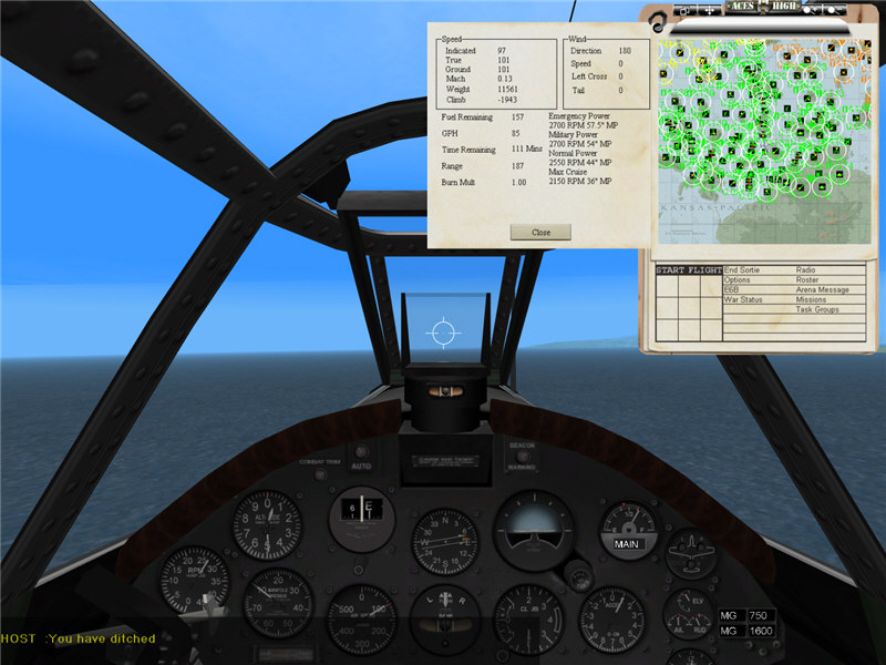
Clean (flaps up, gear up), power off, riding the stall in steady-state descent.

Clean (flaps up, gear up), power on, riding the stall in steady-state descent.
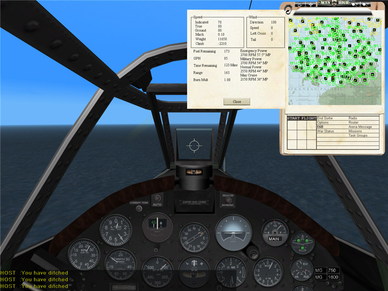
Dirty (flaps full down, gear down), power off, riding the stall in steady-state
descent.

Dirty (flaps full down, gear down), power on, riding the stall in steady-state
descent.
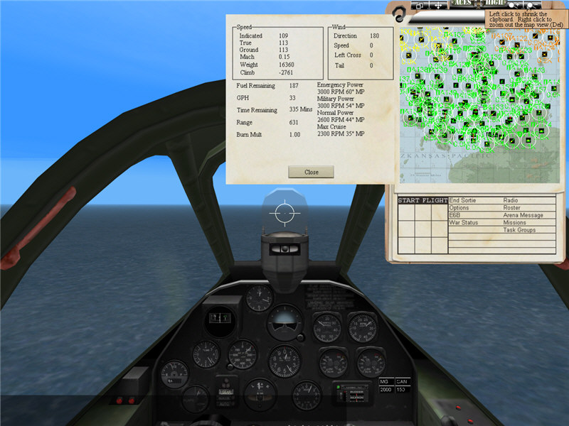
P-38J, clean, power off.
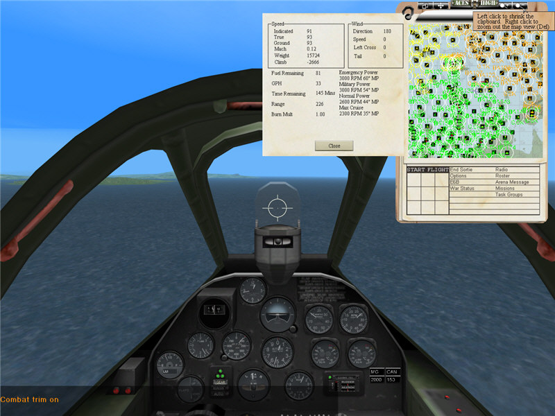
P-38J, flaps and gear down, power off.
[PH.] Airplane Performance Stability and Control, by Courtland D. Perkins and
Robert E. Hage.
[VM.] Theory of Flight, by Richard Von Mises.
[RS.] Fundamentals of Flight, Second Edition, by Richard S. Shevell.
[BM.] Aerodynamics Aeronautics and Flight Mechanics, Second Edition, by Barnes
W. McCormick.
[FD.] America's Hundred Thousand, by Francis H. Dean.
by Brooke P. Anderson
e-mail: Brooke@electraforge.com
Click here to go back to my main gaming page.